

In an energy storage system, “closed loop” refers to the digital communication and control between different components from different manufacturers.
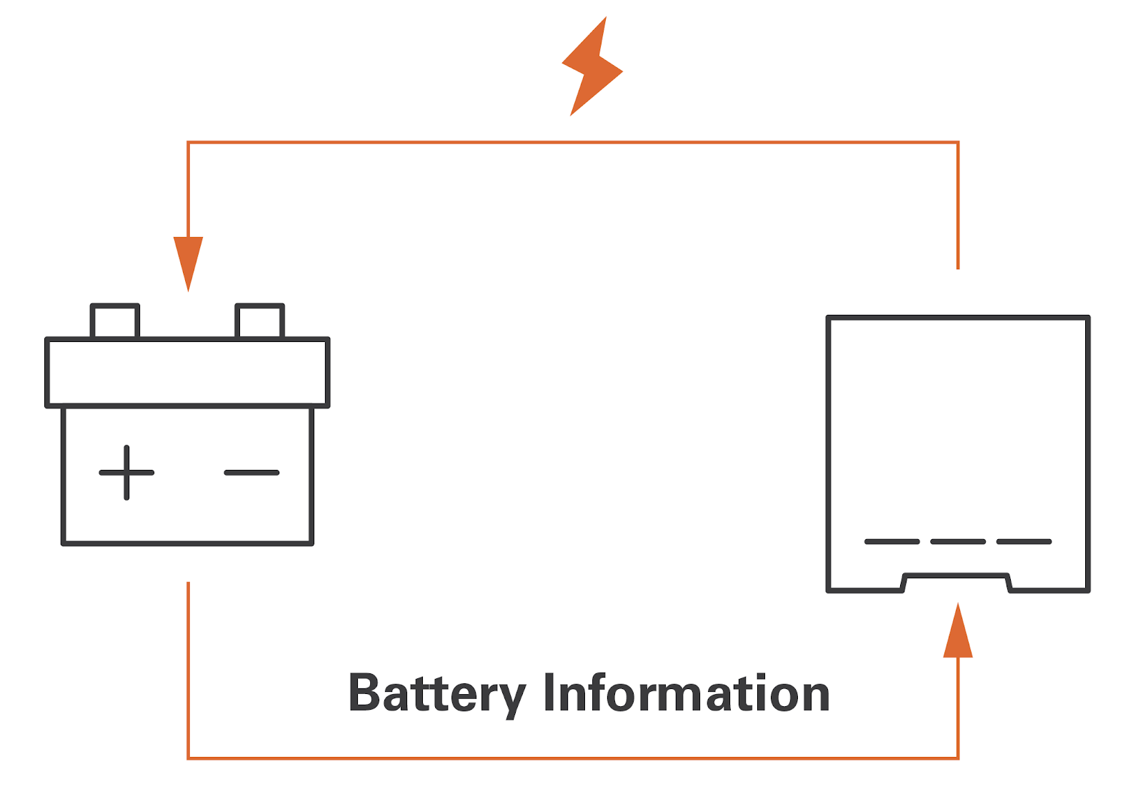
In a battery energy storage system (BESS), the battery management system (BMS) shares with the inverter-charger the battery's present state of charge (SOC), voltage, current and cell temperature as well as the requested charge voltage and current. The inverter-charger uses the information shared by the BMS to adjust its charge settings, thereby closing the loop (see diagram below).
Figure 1. Closed-Loop Communication
Conversely, an “open loop” system refers to a charging system where the battery BMS does not share information with the inverter-charger during the charging process. In an open-loop system, you must manually program the inverter-charger with fixed charge parameters. And potentially use external tools, such as a battery shunt or temperature compensation sensor, to give the inverter-charger information about the current, battery temperature, and calculated battery SOC.
Benefits
A closed-loop charging system offers many benefits.
1) Safety
Closed-loop charging supports battery safety by enabling features embedded in the BMS to interact with the charging system’s controls. This typically results in alarms or warnings requesting to stop the charge or discharge.
2) Ease of configuration
Given the automatic communication of the parameter values, the configuration of a closed-loop charging system is much easier than the manual process of configuring settings for an open-loop system.
3) Faster Charging
A closed loop system enables the communication of dynamic charge voltage requests, which can speed up the charging process. Up to 25 to 40% faster than open loop charging.
4) Monitoring
A closed-loop system can allow the inverter-chargers monitoring system to display accurate battery SOC and other parameters provided by the BMS.
Battery Management Systems (BMS) and Safety
A BMS in a closed-loop charging system can communicate with other devices in the system enabling safety mechanisms. Typically, the BMS prevents charging when there is over-temperature, under-temperature, over-voltage, or over-charge current. The BMS also typically prevents discharge when there is over-temperature, under-temperature, under-voltage or over-discharge current. Except for an under voltage condition, the BMS In a closed-loop system can also communicate that the issue has been cleared and automatically enable discharging or charging to resume.
For example, if a lithium battery is charged when it is below 0 °C (32 °F), the battery loses capacity and its internal resistance is permanently increased before ultimately failing. To avoid under-temperature charging, the BMS in a closed-loop system can terminate the charging process when the battery cell temperature is below 0 °C (32 °F) and restart when cell temperatures rise above the threshold.
A good example of this is the BMS in Discover’s AES RACKMOUNT lithium battery, which is configured to operate only in a safe temperature range. It stops receiving a charge when the battery cell temperature is below 4 °C (39.2 °F) and only resumes charging after 120 seconds have elapsed and the battery cell temperature is 4 °C (39.2 °F) or higher. Discover also offers a AES RACKMOUNT battery model that comes with internal heating that allows it to maintain operating in colder climates.
Configuration
A closed-loop system minimizes the amount of setup required by enabling the BMS to automatically communicate the charging parameters to the inverter-charger.
To enable closed-loop communication, the BMS must use the correct inverter-charger protocol and be hardwired, usually by CAT5 cable, with the inverter-charger. Many batteries come pre-installed with the preferred protocol. However, the wiring of CAN High, CAN Low, and CAN Ground and serial cable signals differ between inverter chargers. This can often be confusing to installers and requires the ability to crimp and install custom CAT5 crossover cables correctly. Always, refer to the inverter-charger documentation for wiring information.
Batteries networked in closed-loop communication with the power conversion system must also take into account the state of charge across multiple batteries which is often coordinating the output of multiple inverter-chargers. How battery data is amalgamated and whether an inverter-charger acts as a client or server needs to be coordinated. To do this many Lithium batteries require the manual setup of the master-slave relationship between batteries and power conversion equipment using DIP switches on the battery modules.
An advantage offered by Discover’s lithium battery systems is the LYNK II Communication Gateway, which supports closed-loop communication between Discover Lithium batteries and various brands of inverter chargers. The LYNK II provides a protocol gateway between the inverter-charger network and the Discover Lithium battery network.
LYNK II is also used to select signal wiring requirements of the inverter-charger so that no crossover CAT5 cables are required. In most cases, no further setup is required, as Discover lithium batteries manage the battery network automatically.
Figure 2. LYNK II between a Discover Lithium Battery Network and the inverter Protocol Network.
Dynamic Charging
In addition to communicating basic battery information, such as the battery capacity, battery SOC, and maximum charge parameters (voltage, current), some inverter chargers support receiving dynamic charge requests from the battery.
Dynamic Charging in a closed-loop system enables faster charging than is normally possible with the conservative static charge voltage targets used by an open-loop system. Lithium batteries with Dynamic Charging firmware continually send to the inverter-charger the safe, but optimized voltage and current
settings. In a closed-loop system, the inverter-charger receives these parameters and dynamically adjusts the charge settings.
With dynamic charging, the system automatically adjusts to overcome voltage losses due to cable and terminal resistance and balances the cells at the end of the charge cycle. This results in a longer bulk phase (maximum current) and a shorter absorption phase.
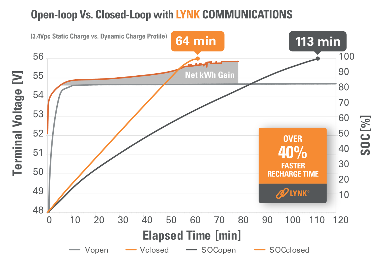
The graph below compares both the static charging and dynamic charging of a Discover Lithium Battery.
Figure 3. Open-Loop vs. Closed-Loop charging times of a Discover Lithium Battery.
Dynamic Cell Balancing
The balancing of battery cells reduces the uneven aging of the cells.
At the end of the charge cycle, as the battery approaches 100% SOC, the BMS adjusts down the overall charge current but forces voltage to rise slightly causing any cell that has diverged from the lowest voltage cell to continue absorbing current safely.
Unfortunately, in an open-loop charging system, maintaining a high target balancing charge voltage often causes individual cells to trigger battery over-voltage protection, which prematurely stops the overall cell balancing process. This results in a shorter balancing period with cells remaining unbalanced. This shortens the useful battery life.
A BMS with Dynamic Balancing controls the target voltage to within a safe range avoiding the premature stoppage of the process. The result is a longer, more thorough cell-balancing process that delivers the longest useful battery life possible.
Conclusion
The BMS delivers safety, allowing the battery to operate only within acceptable limits. The BMS will provide charge parameters to the inverter-charger in a close-loop system enhancing safety and simplifying system configuration. Some BMS will also deliver fast dynamic charging, and dynamic cell balancing in a closed-loop system.
For information about the batteries offered by Discover Energy Systems, please visit: https://www.discoverlithium.com